


-
1
-
2
-
3
-
4
-
5
-
6
-
7
-
8
-
9
-
10
-
11
해당 자료는 3페이지 까지만 미리보기를 제공합니다.
3페이지 이후부터 다운로드 후 확인할 수 있습니다.
3페이지 이후부터 다운로드 후 확인할 수 있습니다.


본문내용
First, we will model the system of pendulum system. This time, our model would slightly be different from that of previous experiment. The reference angle of the pendulum is downward. Therefore, when there is a pendulum below, the angle becomes zero.
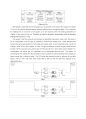
Following figure kinetic diagram of our crane parameters.
Symbol Meaning Value
M mass of the cart 1 [kg]
m mass of the pendulum 0.2 [kg]
l length of the pendulum 40 [cm]
b friction coefficient of the cart 0.5 [kg/s]
r ball screw pitch 1.27 [cm]
Km motor torque constant 4.9 [Ncm/A]
Kb motor back emf constant 0.0507 [V/rad/s]
R motor resistence 0.3 [Ω]
Analyzing this nonlinear model, we’ll first have to achieve the center of mass of the pendulum (x_G ,y_G).
x_G=x-lsinθ,y_G=-lcosθ
Further, apply Newton’s 2nd law to the pendulum system.
∑▒F:Mx ̈+bx ̇+m(x_G ) ̈=F
∑▒〖M:m(x_G ) ̈lcosθ-m(y_G ) ⃛lsinθ=mglsinθ〗
Total system’s net force will equal to sum of net force of cart, net force of pendulum, friction force of cart. Also, total system’s net torque will equal to sum of net torque of cart and pendulum.
추천자료
 [부산대학교 기계공학응용실험] 모터제어실험 PLC 응용실험 & 모터의 종류, 모터의 구조,...
- 전기공학실험 위상전력제어 실험 예비 레포트
 연세대학교 전력 및 제어공학실험 제어실험 5주차 ELECTRIC POWER AND CONTROL ENGINEERING L...
- 연세대학교 전력 및 제어공학 실험 제어파트 2주차 ELECTRIC POWER AND CONTROL ENGINEERING ...
- 연세대학교 전력 및 제어공학 실험 제어파트 1주차 ELECTRIC POWER AND CONTROL ENGINEERING ...
- 연세대학교 전력 및 제어공학 실험 chapter27-30ELECTRIC POWER AND CONTROL ENGINEERING LAB...
- 연세대학교 전력 및 제어공학 실험 chapter23-26 ELECTRIC POWER AND CONTROL ENGINEERING LA...
- 연세대학교 전력 및 제어공학 실험 제어파트 3주차 ELECTRIC POWER AND CONTROL ENGINEERING ...
- 연세대학교 전력 및 제어공학 실험 chapter36-38 ELECTRIC POWER AND CONTROL ENGINEERING LA...
- 가격20,000원
- 페이지수11페이지
- 등록일2018.12.16
- 저작시기2018.11
- 파일형식기타(docx)
- 자료번호#1074436

본 자료는 최근 2주간 다운받은 회원이 없습니다.


소개글